MotorSolve | DCM ModulePMDC and Wound Field Motor Design Software
MotorSolve DCM is the only motor design software you need to get an accurate and complete prediction of your machine's performance. Our powerful automated finite element analysis engine is embedded inside, therefore no model exporting or additional software is required.
 MotorSolve | DCM module
 MotorSolve | DCM module Results
Features
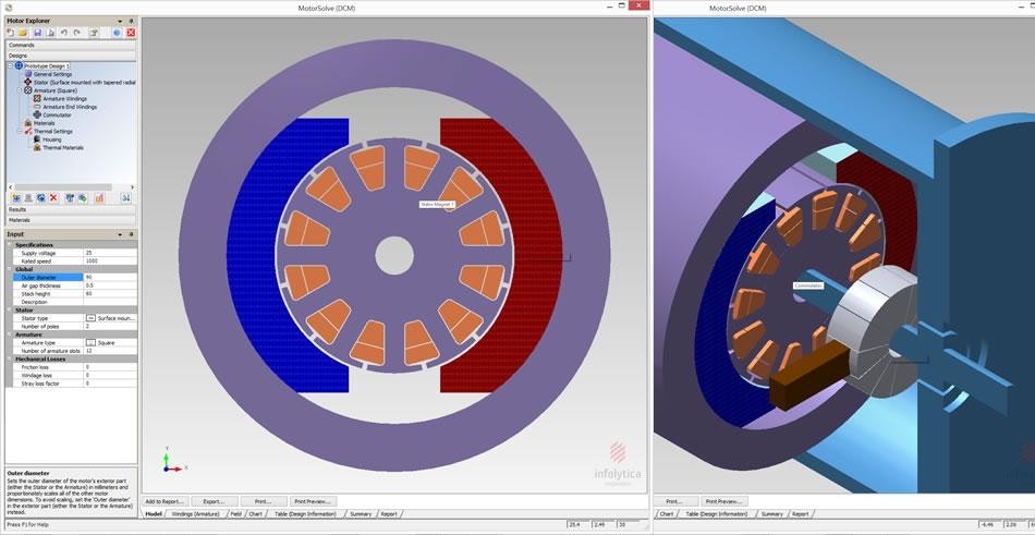
MotorSolve DCM uses a template-based interface which makes creating new designs from scratch effortless - just enter the number of rotor and stator poles and then specify information such as:
- Outer diameter
- Stack length
- Configuration of the brushes and commutator
- Winding
- Lamination material
DCM is the MotorSolve module which includes the brushed DC, permanent magnet DC (PMDC), wound field and universal motor templates.
MotorSolve DCM Workflow
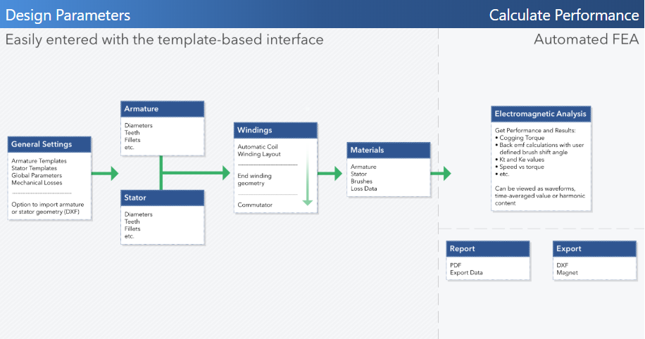
MotorSolve DCM is the easy-to-use software for modeling, simulating and predicting the performance of brushed DC, permanent magnet DC (PMDC), wound field and universal motors. The software has been tailored with a motor designer's needs in mind, making it easy to analyze and optimize any of the motor topologies supported by the DCM module.
The rapid and accurate results are based on automated FEA simulations. There are different analysis methods included, which gives the user control the level of refinement (accuracy vs time).
Templates and Design Parameters
- Brushed DC, PMDC, wound field and universal motor templates
- For wound field: series, shunt and separately excited
- Geometric dimensions of the armature and stator
- Number of rotor and stator poles can be arbitrarily large
- Polyphase machines supported
- Select laminations, brushes and wire materials from extensive database
- Skew & skew prediction for zero cogging torque
All standard slot types (square, round, slotless, parallel tooth, etc) are also included.
Custom rotor and stator geometries can be imported.
Winding Layout
- Select from a list of automatically calculated layouts
- Detailed end winding geometry
- Lap and Wave winding
- Progressive and regressive option
- Supports several wire sizing methods
- User defined multiplicity setting
- Relevant factors (winding factor, fill factor, etc) are automatically calculated
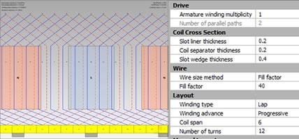 MotorSolve DCM winding diagram and winding settings input
Charts, Fields and Motor Performance
Performance Charts
- Cogging torque
- Kt and Ke values
- Speed vs Torque
- Back-EMF calculations with user defined brush shift angle
- And many more
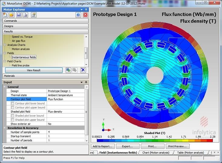
Field Plots
- Flux function
- Flux density
- Surface force density
- Current density
- Winding losses
- Demagnetization prediction and effects based on irreversible model
- And many more
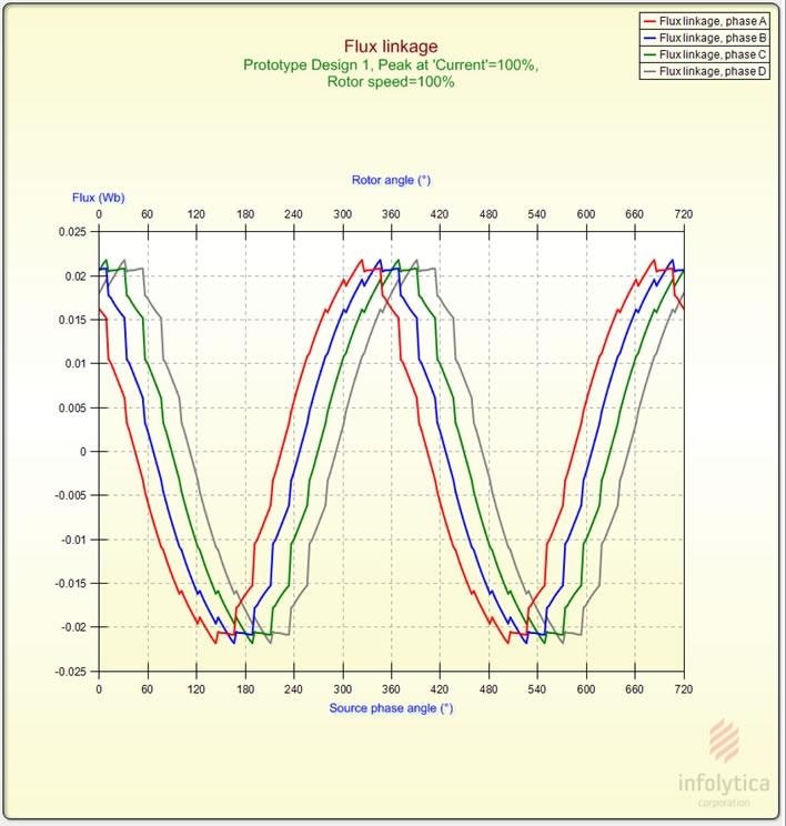 Flux Linkage
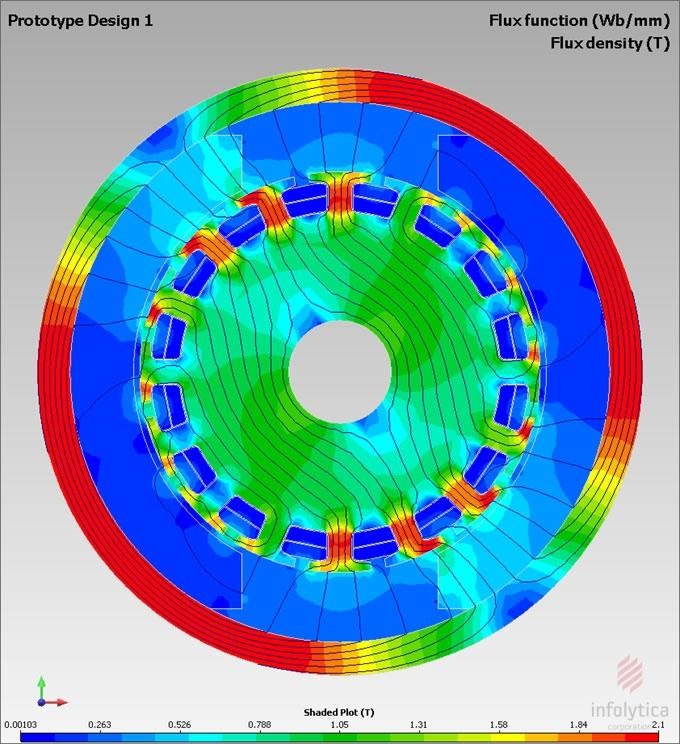 Flux Density Plot
Scripting
Powerful scripting capability for customization, batching and optimization: All MotorSolve commands can be accessed through APIs. Use this feature with any programming language or any ActiveX compliant application, (e.g. Microsoft Excel).
Auto Sizing
An initial value for several parameters related to the size of the machine based on:
- torque per unit volume
- rated current density
Report and Output
- Design parameters, performance data and summary comparisons can be recorded in an experimental log or report (PDF)
- Results are easily accessible either with the use of the clipboard or export functionality
- The summary feature compares two or more designs side-by-side and highlights the differences in design data
Export Options
- MagNet
- DXF
- Data export (as table or chart)
DCM Analysis
MotorSolve DCM calculates machine performance based on automated finite element analysis simulations. There is no need to construct the model, perform mesh refinements and extensive post-processing to extract motor related results. MotorSolve performs these operations for the user.
Using the template interface, a desired waveform, quantity or field is selected with the operating conditions specified.
Current-driven analysis
- Models the DC supply as a constant current source. This allows the simulation to converge much more quickly to the steady-state
- Ideal for servo applications where the motor is controlled by a PWM drive to achieve a specified torque
Voltage-driven analysis
- Perform a full time-stepping non-linear FEA simulation
- Highly accurate for all types of operating conditions and ideal for final design verification