MotorSolve | BLDC ModuleBrushless DC and Permanent Magnet AC Motor Design Software
MotorSolve BLDC is the only motor and generator design software you need to get an accurate and complete prediction of your machine's performance. Our powerful automated finite element analysis engine is embedded inside, therefore no model exporting or additional software is required.
 The BLDC module includes brushless DC, synchronous and permanent magnet AC machine (PMAC) templates.
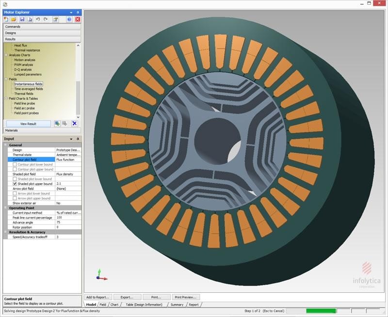
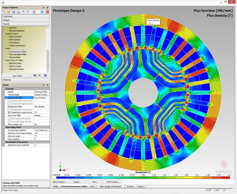 MotorSolve | BLDC module Results
Features
Performance cannot be predicted by general approximations and magnetic circuit calculations alone. MotorSolve BLDC performs accurate FEA-based machine simulations to:
- Predict performance properly when there is saturation
- Account for all loss sources, such as eddy current and hysteresis
MotorSolve BLDC version 6 offers user an optional Generator Analysis feature. The set of loads, parameters and results can be applied to both AC generators and motors operating in the generating mode.
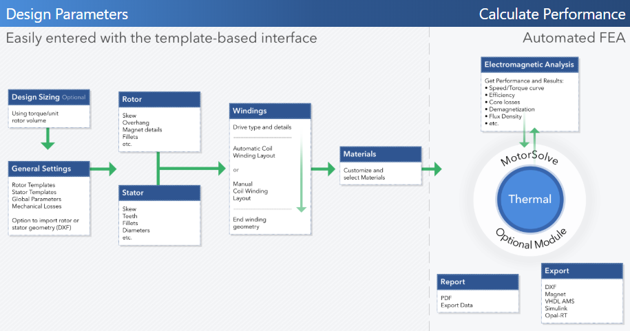
MotorSolve BLDC Workflow
Recent Improvements
- New coil definition tool which detects current path and direction
- Significant speed up due to new algorithm for Newton convergence
- Algorithmic parallelism improvements in all 2D and 3D solvers
- Improved nonlinear surface impedance approximation
- Easily model laminations with the perfect electric insulators boundary condition
- Predict the surface force density on a component
- Multicore mesh generator, solvers and post-processor for even faster results
MotorSolve BLDC is easy to use. Model, simulate and predict the performance of brushless DC and permanent magnet AC machines. The software makes it simple to analyze and optimize both motors and generators.
The rapid and accurate results are based on automated finite element simulations. There are several analysis methods available. Read more about the motor analysis types and generator analysis types in MotorSolve BLDC.
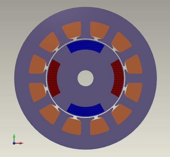
Templates and Design Parameters
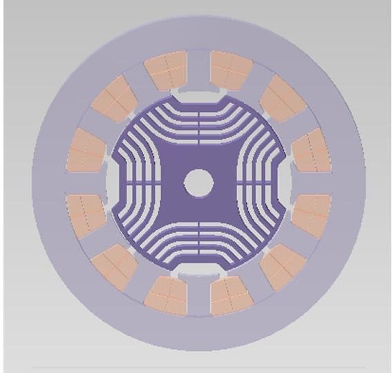 Synchronous Reluctance
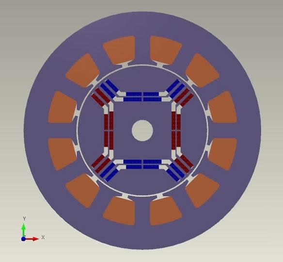 Interior Permanent
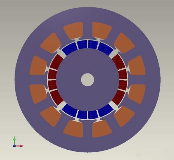 Surface Mounted
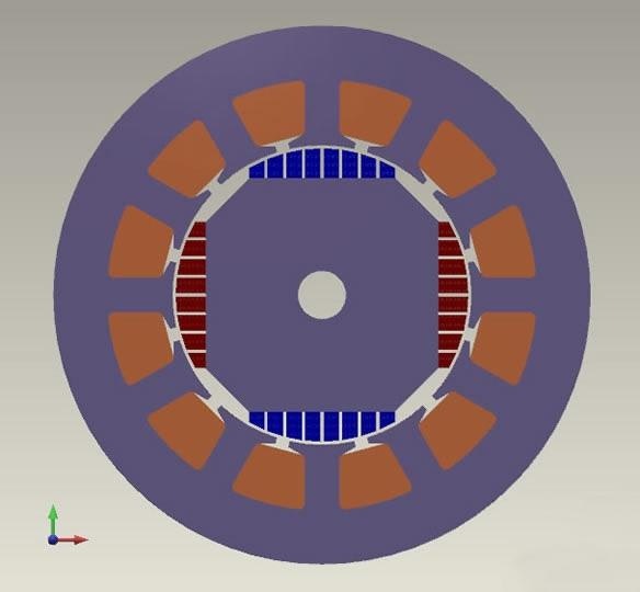 Bread-loaf
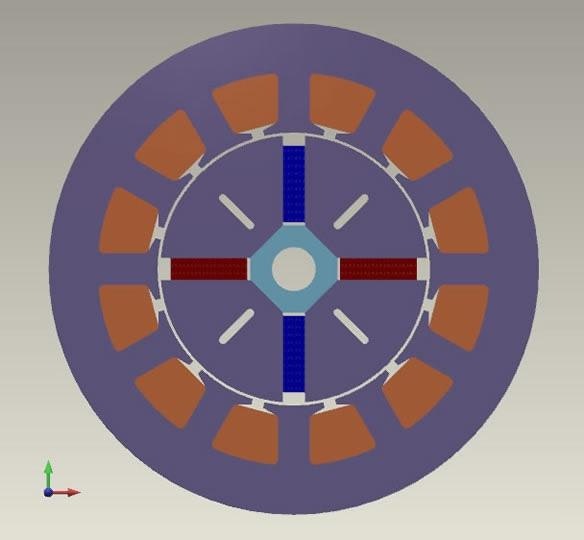 Spoke
Spoke
 Inset
Inset
All standard slot types (square, round, slotless, parallel tooth, etc) are also included.
Custom rotor and stator geometries can be imported.
Design Parameters
- Geometric dimension of the magnets, teeth and slots
- Number of poles and slots - can be arbitrarily large
- Stack length
- Lamination, coil and magnet material
- Temperature for each component
- Skew & skew prediction for zero cogging torque
Winding Layout
- Coil winding layout: Select from a list of automatically calculated balanced layouts or specify via manual entry
- Detailed end winding geometry
- Supports several wire sizing methods
- Relevant factors are automatically calculated
-
Winding charts available
- Phase Back-EMF
- Line-line Back-EMF
- Back-EMF harmonics
- Phase flux linkage
- Winding factors
- Görges diagram
- Airgap MMF
- Animated Airgap MMF
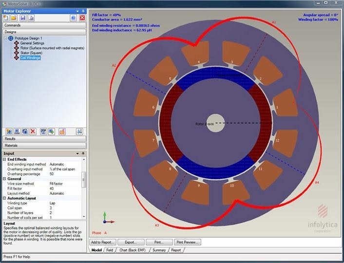 Coil winding layout
Meshing Tools
Output Waveforms and Charts
- Current
- Back-EMF
- Torque
- Flux Linkage
- Phasor Diagram
- And many more
Performance Calculations
- Torque
- Efficiency
- Air Gap Flux
- Cogging Torque
- Several Efficiency Maps for Motors & Generator (Torque, Loss, Power Factor, etc)
- And many more
Field Plots
- Demagnetization prediction and effects based on irreversible model
- Flux density
- Hysteresis, eddy current, iron and total losses
- Surface Force Density
- And many more
Drives
Drives can be treated as either ideal or PWM, supporting both wye and delta connections.
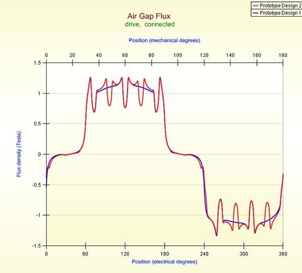 Comparing air gap flux of two designs
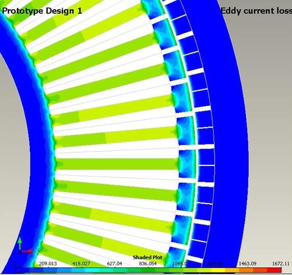 Field Plot: Eddy Current Loss
Generator Performance, Charts & Fields
Output Waveforms and Charts
- Load Power Factor
- Load Impedance
- Output Power
- Efficiency
- Losses
- Phasor Diagram
- And many more
Performance Calculations
- Voltage regulation
- Voltage vs. Current
- Power vs. Speed
- Torque vs. Load Angle
Field Plots
- Demagnetization prediction
- Flux density
- Hysteresis, eddy current, iron and total losses
- Surface Force Density
- And many more
Drives
Drives can be treated as either ideal or PWM, supporting both wye and delta connections.
Scripting
Powerful scripting capability for customization, batching and optimization: All MotorSolve commands can be accessed through APIs. Use this feature with any programming language or ActiveX compliant software (e.g. Microsoft Excel).
Auto Sizing
An initial value for several parameters related to the size of the machine based on:
- torque per unit volume
- rated current density
MotorSolve | Thermal Module
MotorSolve Thermal is a 3D FEA-based thermal analysis tool for calculating the steady-state temperatures using the losses from BLDC's electromagnetic analysis and perform the electromagnetic analyses at these steady-state temperatures. Read more about MotorSolve | Thermal Module.
Report and Output
- Design parameters, performance data and summary comparisons can be recorded in an experimental log or report (PDF)
- Results are easily accessible either with the use of the clipboard or export functionality
- The summary feature compares two or more designs side-by-side and highlights the differences in design data
Export Options
Powerful scripting capability for customization, batching and optimization: All MotorSolve commands can be accessed through APIs. Use this feature with any programming language or ActiveX compliant software (e.g. Microsoft Excel).
- Simcenter Amesim
- FloMASTER
- MagNet
- DXF
- VHDL-AMS
- Simulink©
- OPAL-RT eDRIVEsim
- Data export (as table or chart)
MOTOR Analysis
MotorSolve BLDC calculates machine performance based on automated finite element analysis simulations. There is no need to construct the model, perform mesh refinements and extensive post-processing to extract motor related results. MotorSolve performs these operations for the user.
Using the template interface, a desired waveform, quantity or field is selected with the operating conditions specified.
MotorSolve BLDC includes several analysis methods, suitable for different phases of the design process. The waveforms, fields and charts are computed using one of the selected analysis method, allowing users to choose the computation time based on their required degree of accuracy.
D-Q & Lumped Parameter Analysis
- Ideal for what-if analysis: initial sizing or design variations
- Rapid: based on a single FEA simulation to characterize the performance
- The component values from the equivalent circuit of the D-Q approximation can also be obtained using the lumped parameter analysis
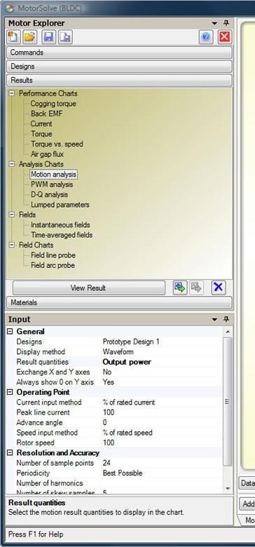 Results: maximum flexibility and control over the waveforms and analysis
PWM Analysis
- Perform a dynamic simulation of the electronic commutation in a three-phase full-bridge
- Squarewave or Sinewave
- Important at high speeds: current waveforms differ significantly from the ideal
- Also supports non-linear PWM analysis method
Motion Analysis
- Perform a full time-stepping non-linear FEA simulation
- Wye or Delta
- Sinusoidal or six-step drive
- Highly accurate for all types of operating conditions and ideal for final design verification
GENERATOR Analysis
MotorSolve BLDC also offers an optional generator analysis feature. The result waveforms and charts, applicable to both motors in generating mode and AC generators, can be computed with one of four different analysis types available.
Operating Points
Generated a chart of the selected quantities related to the short-circuited and maximum power point of the generator. The results are calculated from the nonlinear D-Q model of the motor, obtained from a FEA solve of the currents between 0 and the short-circuit current.
DQ Analysis
- Ideal for what-if analysis: initial sizing or design variations
- Rapid: based on a single FEA simulation to characterize the performance
Reduced Order Model
- Perform a dynamic simulation of the electronic commutation in a three-phase full-bridge
- Squarewave or Sinewave
- Important at high speeds: current waveforms differ significantly from the ideal
- Also supports non-linear PWM analysis method
Motion Analysis
- Perform a full time-stepping non-linear FEA simulation to simulate a generator connected to resistive/inductive load
- Wye or Delta
- Sinusoidal or six-step drive
- Highly accurate for all types of operating conditions and ideal for final design verification